Reducing wear and tear on your equipment and increasing the number of shots
with a level horizon
can be improved by paying attention to the center of gravity of the equipment so
it hangs plumb:
|
An area with little web coverage is that of Centre of Gravity or balancing your rig. Personally, when I started KAP I had some kite, mechanical and electronics skills, but none in tying all this together, and getting things in balance, where do you start?
(x.a) = (y.b)+(z.c) None of this theory helps a lot when you try to bundle together your collection of servos and camera, and try to balance the resulting odd shape, in three dimensions! The rest of this page details how to balance a standard double U KAP rig. Now, every rig is different, each with it's own little personality, so please take the following as it is given, a little help rather than a religious exposition!
The first step is to take the camera, including any metalwork closely associated with it (e.g. servos for shutter release, webcam for viewfinder etc). If necessary use tape to hold it all together in the right place in the absence of the U brackets.
Note the offset from the tripod mount in X and Y when the camera is level as the camera's centre of gravity. If you can't get the camera to level, you'll need a longer L or try a different mounting point. Since the camera is much heavier than the L bracket it probably doesn't make much difference to the balance (<1mm), but for the mathematically challenged you can use the formula at the top of the page to subtract the error caused by the L bracket. Remember that the balance in some cameras may move about significantly as the
lens focuses or zooms. Also remember to include or exclude the batteries as
appropriate!
Now complete the construction of the lower U bracket, EXCEPT
the fixings and holes for the tilt servo. Make sure that all additional elements are
centered along the center line of the bracket, this will ensure you introduce minimal errors
in the Y balance.
Hang the completed bottom bracket from a line as shown right. Adjust the position of the line so that the bracket hangs vertically, you can use a plumb to check this. Mark this point as the pivot point for the bottom bracket. As well as ensuring that the rig stays in balance as the camera is tilted, this also minimises the strain on the tilt servo as it operates. If the two vertical sides of the bottom bracket are too long, cut of the excess (and save weight). Re-balance after this operation as the reduction will make a very small difference in the pivot point. Once you have drilled the holes for the pivot of the bottom bracket (remember these should go through the centre line of the bracket), hang the bottom bracket in it's correct orientation by a single line passing through both holes. Double check that the Y direction is still in balance. Make any small adjustments needed to maintain Y balance, e.g. move tie-wraps, reposition ancillary equipment etc. The bottom bracket is now balanced in both Y and Z directions.
Complete the rig by fixing the pan servo, and connection to the suspension. Small errors in X are normally trimmed out by adjusting the position of the batteries etc normally mounted on the top bracket. Errors in Y (and bottom bracket Z) are less of a problem and can be lived with. They tend to affect the tilt of the camera which can be compensated for by the tilt servo. The Z balance of the top bracket is not important. |
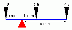 The theory is pretty
straight-forward. The force exerted by x grams at distance a mm from the red
fulcrum must equal the sum of the forces exerted by y and z:
The theory is pretty
straight-forward. The force exerted by x grams at distance a mm from the red
fulcrum must equal the sum of the forces exerted by y and z: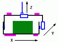 First of all, lets get our
bearings. We are trying to balance a double U rig like this one. It has a camera
(green) which may include some additional metalwork and/or servos for control,
various other ancillary equipment (purple), and blue tilt and pan servos. I will
use the convention for direction shown in the diagram for the X, Y and
Z
direction. The method I describe is mostly empirical, you maintain balance as
the rig is constructed. To make things easy I try to ensure that the centre of
gravity in the Y direction always runs through the center of both U
brackets.
This is not essential, but it is desirable as it simplifies construction.
First of all, lets get our
bearings. We are trying to balance a double U rig like this one. It has a camera
(green) which may include some additional metalwork and/or servos for control,
various other ancillary equipment (purple), and blue tilt and pan servos. I will
use the convention for direction shown in the diagram for the X, Y and
Z
direction. The method I describe is mostly empirical, you maintain balance as
the rig is constructed. To make things easy I try to ensure that the centre of
gravity in the Y direction always runs through the center of both U
brackets.
This is not essential, but it is desirable as it simplifies construction. 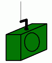 Find the
center of gravity
for X and Y directions of the camera as follows. Find a convenient point to
attach the camera to a kite line. This may be the tripod mount on the base.
Don't worry if the camera ends up being upside down, we are not interested in
the Z direction at the moment. Fashion a L shaped fixture as shown in the
diagram, I used a nylon bolt for the tripod mount, and a small piece of
aluminium. Keep the weight of the fixture as low as possible to reduce errors.
By hanging the camera from the line, and rotating the L it should be possible to
achieve a level camera in the X and Y direction, but not necessarily both at once.
Find the
center of gravity
for X and Y directions of the camera as follows. Find a convenient point to
attach the camera to a kite line. This may be the tripod mount on the base.
Don't worry if the camera ends up being upside down, we are not interested in
the Z direction at the moment. Fashion a L shaped fixture as shown in the
diagram, I used a nylon bolt for the tripod mount, and a small piece of
aluminium. Keep the weight of the fixture as low as possible to reduce errors.
By hanging the camera from the line, and rotating the L it should be possible to
achieve a level camera in the X and Y direction, but not necessarily both at once. 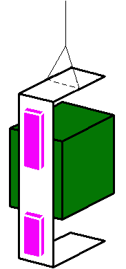 Now
we'll balance the bottom bracket's Z direction, this is so that balance
is maintained as the camera tilts.
Now
we'll balance the bottom bracket's Z direction, this is so that balance
is maintained as the camera tilts.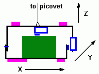 Now fabricate the top
bracket including the tilt servo,
Now fabricate the top
bracket including the tilt servo,